

ผลิตภัณฑ์ทั้งหมด
-
เกจวัดความดันแตกต่าง
-
เกจวัดแรงดันดิจิตอล
-
เกจวัดแรงดันสแตนเลส
-
เครื่องส่งสัญญาณความดันแม่นยำ
-
คอนโทรลเลอร์ลอจิกที่ตั้งโปรแกรมได้
-
สวิตช์ระดับลอย
-
ตัวกำหนดตำแหน่งวาล์วนิวเมติก
-
เซ็นเซอร์ส่งสัญญาณอุณหภูมิ
-
Hart Field Communicator
-
โซลินอยด์วาล์ว
-
วาล์วควบคุม
-
เครื่องวัดอัตราการไหลความแม่นยำสูง
-
ปั๊มน้ำใต้น้ำ
-
ท่อร่วมส่งแรงดัน
-
เครื่องวัดระดับอัลตราโซนิก
-
เครื่องวัดกระแสไฟแรงดันไฟ
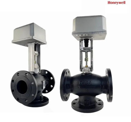
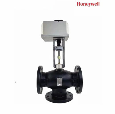
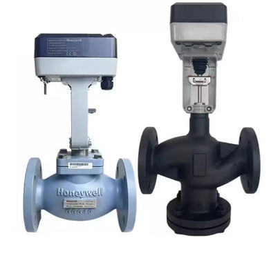
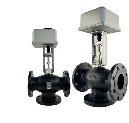
Honeywell ML7421 พันธมิตรการควบคุมอินทิกรัล แอลเวลอุณหภูมิไฟฟ้าสองทาง วัสดุติดต่อทองแดงปรับความแรง


| สถานที่กำเนิด | - |
|---|---|
| ชื่อแบรนด์ | Honeywell |
| ได้รับการรับรอง | - |
| หมายเลขรุ่น | ML7421 |
| จำนวนสั่งซื้อขั้นต่ำ | 1 |
| ราคา | USD200/PC |
| รายละเอียดการบรรจุ | ต้นฉบับ |
| เวลาการส่งมอบ | 2 สัปดาห์ |
| เงื่อนไขการชำระเงิน | L/C, D/A, D/P, T/T, Western Union, MoneyGram |
| สามารถในการผลิต | 1000 |
รายละเอียดสินค้า
| ชื่อสินค้า | วาล์วควบคุมอุณหภูมิ วาล์วปรับสมดุลแบบไดนามิก | แพ็คเกจ | กล่องกล่องเดิม |
|---|---|---|---|
| คุณภาพ | ใหม่และต้นฉบับ | ระดับไอพี | IP20 |
| วัสดุติดต่อ | ทองแดง | ||
| เน้น | วาล์วอุณหภูมิไฟฟ้าสองทาง,ML7421 วาล์วควบคุมสมบูรณ์แบบสัดส่วน |
||
รายละเอียดสินค้า
คุณลักษณะ • การติดตั้งอย่างรวดเร็วและง่าย • ไม่จําเป็นต้องเชื่อมต่อแยกกัน • 3/4 นิ้ว (20 มม.) ดวงบน ML7421A; 1-1/2 นิ้ว (38 มม.) ดวงบน ML7421B • ไม่จําเป็นต้องปรับ• การวางวาล์วให้ถูกต้อง. • สามารถเลือกสัญญาณเข้า 0 ((2) ถึง 10 Vdc/0 ((4) ถึง 20 mA. • การตอบสนองตําแหน่ง. • สวิทช์ปลายจํากัดแรง. • ผู้ประกอบการด้วยมือ. • การกระทําโดยตรงหรือกลับ • มอเตอร์ร่วม.• การออกแบบที่ทนทานต่อการกัดกรอง. • ฟรีการบํารุงรักษา
ทั่วไป ใน ML7421, การขับเคลื่อนของมอเตอร์ร่วมเปลี่ยนเป็นการเคลื่อนไหวเชิงเส้นของกระดานการดําเนินการโดยใช้การส่งเกียร์หนอน.คลิปการยึดปุ่มเชื่อมสตางค์ actuator กับสตางค์วาล์ว. เซ็นเซอร์แรงภายใน, โดยใช้ไมโครสวิตช์ที่ติดตั้ง, ปิดตัวขับเคลื่อนเมื่อแรงสตัมที่กําหนดการใช้งานด้วยมือ ML7421 มีตัวปุ่มการใช้งานด้วยมือ (ดูรูป. 7) เปิดหรือปิดวาล์วในกรณีขาดไฟฟ้า ปิดหรือตัดไฟฟ้าก่อนใช้มือ ML7421.ดันลงหมุนมือมือถือผู้ประกอบการและหมุนหมุนหมุนตรงข้ามทิศทางนาฬิกาเพื่อเคลื่อนไหวต้นลงหรือทิศทางนาฬิกาเพื่อเคลื่อนไหวต้นขึ้น. หากตัวขับเคลื่อนถูกนํากลับไปควบคุมอัตโนมัติ, ปุ่มมือการทํางานจะเปิดล็อคโดยอัตโนมัติ.มันหมุนไปเพียงระยะสั้นๆ ก่อนจะตัดกันโดยอัตโนมัติ โดยไม่ต้องใช้พลังงานสําคัญ: การทํางานด้วยมือทําให้แรงปิดสูงมากที่สามารถติดหมุนการดําเนินงาน, เกินการตั้งค่าของสวิทช์แรง, และหยุดมอเตอร์หลังจากการทํางานปิดคลุมด้วยมือ, ปล่อยหมุนหมุนหนึ่งโดยการหมุนหมุนหมุนมือเครื่องมือเพื่อให้เครื่องมือมือมืออัตโนมัติออกเมื่อการต่อเนื่องพลังงานสัญญาณเข้า (+) ระยะสัญญาณเข้าแบบแอนาล็อก (+) ตั้งไว้ที่โรงงานที่ 0 ถึง 10 Vdcการเปลี่ยนตําแหน่งของสล็อตตัวเลือก W2 กําหนดช่วงที่ 2 ถึง 10 Vdc การเปลี่ยนตําแหน่ง W4 เป็น mA (ดูรูป 8) ระยะที่ 0 ((4) ถึง 20 mAW3 และ W4 ตั้งอยู่ด้านหลังของแผ่นป้องกัน PCB.ดูรูป 8 สําหรับตําแหน่งของพล็อกตัวเลือก.รูป 7. ML7421A,B ปุ่มมือผู้ใช้เครื่องขับเคลื่อนสามารถตั้งให้ทํางานในหนึ่งในสามตําแหน่งในกรณีสัญญาณล้มเหลว: 1. 0% ราคาตัวประกอบตรงกับสัญญาณ 0 หรือ 2 Vdc 2. 50% ราคาตัวประกอบตรงกับตําแหน่งกลาง 3. 100% ราคาตัวประกอบตรงกับสัญญาณ 10 Vdcหาก W4 ตั้งอยู่ในตําแหน่ง mA, เครื่องขับเคลื่อนทํางานเสมอ 0%. W1 (W4 ) W3 W4 V![]()
![]()
![]()
![]()
แนะนำผลิตภัณฑ์